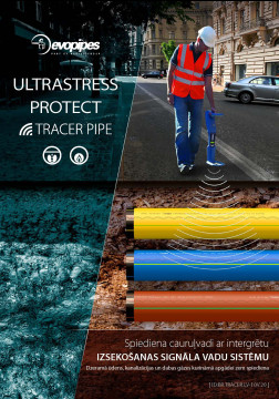
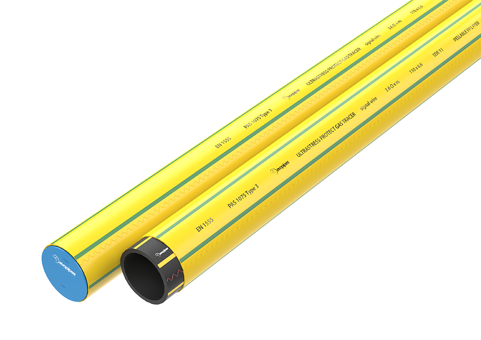
ULTRASTRESS PROTECT GAS TRACER
PE100-RC type gas pipes with integrated signal wires
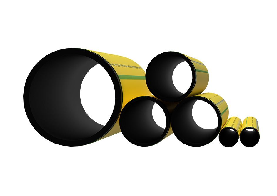
EN 1555, PAS 1075 type 3, DN/OD 32-630 [mm]
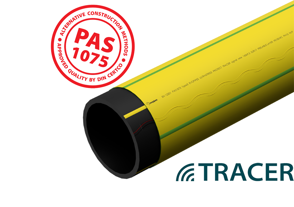
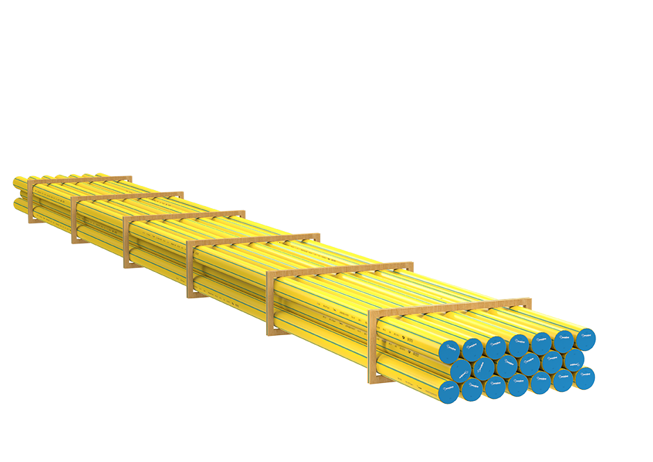
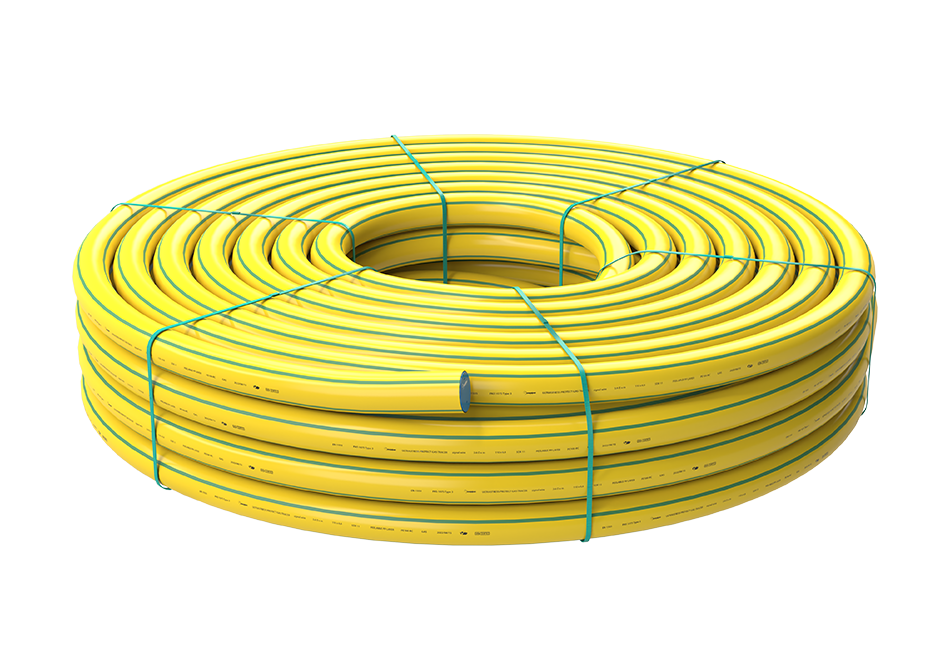
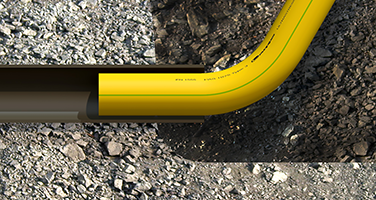
ULTRASTRESS PROTECT GAS TRACER gas supply pressure pipes made from PE100-RC material with integrated signal wires and added polypropylene (PP) protective layer.
 |
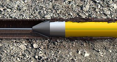
By using TRACER products it is possible to determine the exact location and depth of the pipeline construction and to trace the constructed pipeline without additional earthwork. |
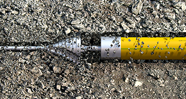
PE100-RC material pipes are resistant to long-term expansion of cracks, scratching, and point-type loads. Point-type loads are especially common during the assembly of the pipelines using trenchless installation methods (for instance, as a result of friction against the stones that are present in the soil). In the case of a point-type load, tension, and plastic deformations are produced in the material, which may cause cracks in the internal surface of the pipe.
PE100-RC pipes with PP coating provide additional durability against scratching in cases of especially complex installation, for
instance, while burst lining.
-
Advantages
- Pipe system with a reliable and accurate location detection system
- Minimum 100 years lifetime
- The protective layer provides maximum resistance to mechanical damage
- Conforms to PAS 1075 Type 3
- High resistance to point-type loads
- Designed for alternative installation methods- horizontal directional drilling, relining, and bursting
-
Construction methods
For traditional (open trench) installation:
- In open trenches without bedding and filling according to EN 1610, EN 1046, EN 12327, EN 12007-2 (does not apply to soil-filled in around the pipe)
For alternative installation methods:
- Laying into the soil with a plough or a milling cuter according to EN 1610, EN 1046, EN 12327, EN 12007-2 (does not apply to soil-filled around the pipe)
- Horizontal directional drilling according to EN 12889, EN 14457
Horizontal directional drilling is used for the construction of new or the reconstruction of old pipelines. The old
pipelines can remain fully functional during the reconstruction. Only short term interruptions of work may occur in order to
perform new connections. Use of this method is suitable for areas where trench works must be avoided due to, for instance:
water bodies, roads and railroads, squares, buildings, etc.- Drawing into the old pipe (relining) according to EN 12889, EN 14457
Relining method is used for the reconstruction of old pipelines. ULTRASTRESS pipe with a slightly smaller diameter is drawn into the
old pipe. This method is used in several cases of reconstruction. Only the beginning of the pipeline span has to be reconstructed
and junctions of the pipe are excavated during the works.- Burst lining according to EN 12889, EN 14457
Burst lining is used if the old pipeline is heavily deformed or its diameter does not conform with the new requirements. A hydraulic burst
head is used as the guide, which builds the way for the new pipe. The specific nature of the method permits the drawing in of a
pipe of the same diameter or larger than the existing one. Advantages of the method:- Reconstruction of easily bursting pipes made of materials like ceramic, concrete, cast iron, polymer, steel, etc. is possible.
- The flow rate parameters of the new pipe are higher or equal to the throughput capacity of the reconstructed pipe (drawing
in of a pipe with a larger diameter is possible). - Compact equipment permits operation in restricted conditions.
Pipe welding operations:
Buttfusion welding should be carried out according to ISO 12176-1 standard requirements.
Electrofusion jointing should be carried out according to ISO 12176-2 standard requirements.
-
Technical information
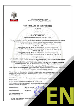
- Certified to PAS1075 type 3*
- Dimensions of the pipe conform to EN 1555
- Core pipe from high-density polyethylene (HDPE), type PE100-RC
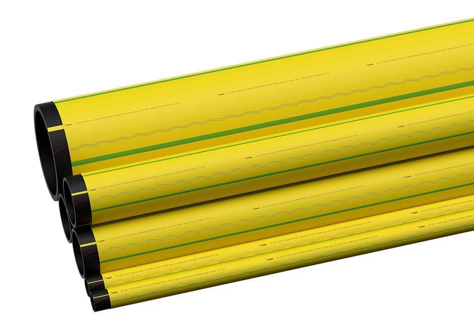
- Peelable protective layer from polypropylene (PP)
- Protective layer thickness: ~10% of the thickness of the core pipe wall thickness
- Green stripes identify additional PP protective layer
- Two signal wires, laminated into polyester tape:
- Signal wire isolation material - polyamide (PA)
- Colour - red and black
- Signal wire material - stainless steel
- Diameter of signal wires 0.5 [mm]
- Cross-sectional area 0.2 [mm2]
- Following ISO/TR 10358 and ISO/TR 7620, the pipes and fittings possess chemical resistance between pH 2 (acid) and pH 12 (alkaline)
Pipe dimensions:
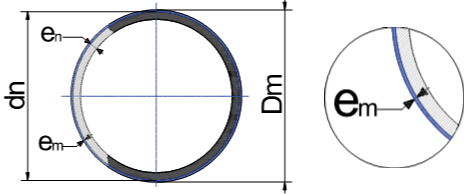
dn en [mm] em (±10%) [mm] Dm [mm] SDR11^ 32 3.0 ~0.9 33.8 40 3.7 ~1.0 42 63 5.8 ~1.0 65 90 8.2 ~1.5 93 110 10.0 ~1.8 113.6 125 11.4 ~2.0 129 160 14.6 ~2.0 164 180 16.4 ~2.0 184 200 18.2 ~2.0 204 225 20.5 ~3.0 231 250 22.7 ~3.0 256 280 25.4 ~3.0 286 315 28.6 ~3.0 321 355 32.2 ~4.0 363 400 36.3 ~4.0 408 450 40.9 ~4.0 458 500 45.4 ~4.0 508 560 50.8 ~5.0 570 630 57.2 ~5.0 640 EVOPIPES PIPE CLASSIFICATION ACCORDING TO PAS* 1075
* PAS = Publicly Available Specification serves as an addition to the existing system of normative acts and directives and refers to polyethylene pipes that are intended for installation using alternative construction methods.

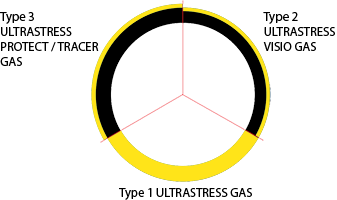
Type 1 – monolith wall pipe made of PE100 – RC material.
Type 2 – 2 layer pipe made of PE100 – RC material, 10% VISIO layer, 90% base layer.
Type 3 – monolith wall pipe made of PE100 – RC material with polypropylene (PP) protective layer, the green lines identify additional protective layer.
-
Product catalogue
ULTRASTRESS PROTECT TRACER Catalogue LV
Pressure pipes with integrated tracing signal wires
Download